Turnkey and Trenchless projects for OFC Laying
AICIPL, OFC Division, undertakes all the works/services listed alongside and explained below to cater the needs of individual Customers on need based standards.
Optical Fiber Cable Works includes the following
- Total Design
- Route Survey
- Right of Way permissions
- Civil Works
- Trenching and associated Civil works
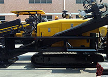
- Horizontal Directional Drilling Boring
Supply and Installation of
- HDPE, GI, RCC, DWC & PVC Pipes
- Cables (OF & Cu)
- Splice Closures
- FDMS
- Electronic route markers
- RCC markers
- Chambers, Manholes, Hand-holes
- Earthing and Link Testing
- Submission of As-built drawings
AICIPL OFC Division analyses and implements
- Optical Fiber Communication Backbone/Access Networks
- Route Survey for OFC routes and obtaining ROWs.
- Execution of OFC Routes.
- Undertaking Acceptance Testing works on behalf of the Client.
AICIPL has wide experience in implementing major OFC projects in record time for Backbone & Access Network . AICIPL has undertaken OFC projects for more than 4,500 kms, for various network operators in India. AICIPL implemented the Access Network Projects based on Optical Fiber Cable for various Telecom Service Providers. The company has executed Access Network Projects covering approximately 500 k.m with OFC route in urban areas. Under Backbone & Access Network implementation The following services are offered.
Route Survey & Design
Extensive route survey is carried out prior to designing the OFC network to obtain the following essential data
- Right of Way demarcation
- Soil strata
- Existing Underground utilities
- Road / Rail / Bridge / River / Canal Crossings
- BOQ Estimation
- Any other criticalities
BOQ Estimation and approval from Customer
On the basis of survey details an estimated BOQ is prepared and submitted to get the approval from the Customer
Supply of Materials
Annu supplies the following material required for construction of Backbone Network.
- HDPE Ducts
- Optical Fiber Cable
- FDMS
- GI/RCC/DWC/PVC Pipes
- Fiber Joint Closures
- Warning Tape
- Pre-cast Chambers
- Route Markers etc.
Right of Way Permissions
On behalf of the client, Annu obtains necessary statutory permissions from regulatory bodies. Single Line Diagram (SLD) is made to determine the jurisdictions and permissions obtained.
- State Highways
- Railway Department
- Roads & Buildings Department
- Municipal corporations
- Panchayath Boards
- Irrigation department
- National Highway Authorities
- Forest Department
- Trenching, ducting and backfilling
Specifications for Excavation of Trenches
- Standard depth will be measured from lower side of natural ground level to the base of the trench.
- Standard depth for normal soil and soft rock: At least 1500 mm (1.5 M).
- Standard depth for hard rock: At least 900 mm (0.9 M) provided the rock stars from earth crust.
- Width of trench: 400mm at top and 300mm at the bottom.
- Different clients have slightly marginal differences in trench depth and we cater to the needs of the customers.
- Outside the city limits trench will normally follow outer boundary of the berm.
- Where the berm has burrowed pits or forestation, or when cable is to be laid along culverts/bridges or cross-streams, trench may be made closer to road edge, or in some cases, over embankment or shoulder of the road.
- Line up of trench would be such that HDPE duct(s) will be laid in straight line, both laterally as well as vertically except at locations where it has to necessarily take a bend because of change in alignment or gradient of trench.
- Minimum radius of two meters will be maintained, where bends are necessitated.
Duct Laying
- Ducts will be laid in a flat bottom trench, free from stones, and sharp edged debris.
- The duct would be placed in trench as straight as possible. However, at bends horizontal and vertical minimum bending radius for duct of 1300 mm would be maintained.
- Ducts will be laid preferably using specially designed dispensers
- Ducts shall be free from twist and collapsed portions. Any such portion will be rectified before backfilling by using couplers.
- Ends of ducts will always be closed with END PLUGS to avoid ingress of mud, water or dust.
- Prior to aligning the ducts for jointing, each length of the HDPE duct will be thoroughly cleaned to remove all sand, dust or any other debris that may clog, disturb or damage the optical fiber cable when it is pulled or blown at a later stage.
- The ducts will be joined with couplers using duct cutter & other tools and will be tightened and secured properly.
- The duct joint will be practically airtight to ensure smooth cable blowing using cable blowing machines.
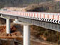
- Gl and / or RCC pipes will be used as additional protection for the HDPE ducts at rail / road crossings, built-up area/city limits, on culverts and bridges, as required.
- Chambering or concreting around RCC/ Gl pipes as additional protection on bridges, culverts and also on stretches wherever depth of excavation is less than specified will be done
- Reinstatement of excavated trench will be done with proper compaction.
Back Filling
- Trench will be initially filled with sieved soil or sand in Rocky Terrain for about 10 cm which will act as a cushion / padding and then duct is placed gently over it.
- After that another layer of 10 cm of fine sieved soil or sand is poured and then entire trench is backfilled with excavated material.
- Under normal soil conditions duct is directly laid in trench and backfilled. Adequate dry compaction will be done before crowning.
Crowning
- When backfilling has been done up to ground level a hump of soil is made to cater for soil settlement.
- Entire excavated soil will be used for back filling.
- Crowning will be confined to width of trench only.
Duct Integrity Test
After backfilling ducts shall be tested for integrity. Two types of tests are conducted, viz., Air Tightness Test and Kink-free Shape test.
Air Tightness Test This is done by pressurizing 2 km of duct stretches at a time, by closing one end of duct and passing compressed air at 5-6kg/cm2 from the other end. When the pressure reaches about 5kg/cm2, the inlet of the duct is closed. Fall in pressure should not be more than 50% in 1(one) hour.
Kink-Free Shape Test To check that duct has not collapsed or kinked a wooden cylindrical piece (shuttle) of size 150 mm long and 0.75 X D mm in diameter, (where 'D' is inner diameter of duct), is blown into the duct with far end fitted with Flexible wire grip/stocking. The wooden shuttle should pass through duct at far end with out any obstruction and within approximately 10 minutes or less.
Fiber Termination
All fibers of Optical Fiber Cables will be terminated on Fiber Distribution Management System (FDMS) at each regenerator (REG) or Add Drop Multiplexer(ADM) location. Installation of FDMS is done according to the manufacturer's specification. End to End testing can be carried out from the FDMS to FDMS using the connectors which are mounted on the FDMS. Survey and Digitized Maps
The survey digitized maps will have the following information:
- Relative position of proposed OFC route with respect to existing cables.
- Marking of Rocky, Submerged and Normal soil terrain.
- Marking of Crossing locations and type of proposed crossing detail viz. HDD, Open cut, and Boring etc.
- Marking of offset availability
- Geographical co-ordinates for all crossing HDPE duct coupling and OFC jointing locations.
- Assessment of required materials.
- Identifying Critical points.
- Demarcation of Right of Way.
Cable Testing
The cable will be tested before pulling/blowing to ensure continuity as well as to check all the parameters in both 1550 nm and 131 nm windows.
Aerial Cabling
At places where open trenching is not possible due to very narrow roads and due to delay in obtaining RoW, aerial cabling will be adopted as a temporary solution. Also by using special cables (ADSS) this will be laid along the Transmission lines for longer distances.
Supply and Installation of Distribution Box
Distribution boxes will be positioned at every location where a main cable is to be distributed to sub - areas with lesser pair cables.
Cable blowing
Cable blowing machine, (Cable jet or any other machine), would be deployed along with a good compressor delivering10 Kg/cm2 pressure and 700 cfm discharge. Cable drum will be loaded on payoff stand & unwound from topside of the drum. Pay off stand would be placed properly secured so that it does not collapse while dispensing OFC.
Fusion splicing
Splicing is done using a good quality splicing machine. Splice loss per joint will be minimum and would not be more than 0.07 dB. In no case average splice loss per link will be more than 0.06 dB x No. of splices. At least 0.6 M to 0.8 M fiber would be stored in cable tray. Fiber would be neatly coiled without kinks. Minimum bending radius of 80mm would be ensured, Joint closure would be sealed properly before it is taken out of the controlled environment free from dust particles and air-conditioned splicing van.
End to End Link Testing
Link Test is carried out on entire section terminated at both ends after completion of tasks to ensure the losses are within permissible limits on all fiber.
Horizontal Directional Drilling
Link Test is carried out on entire section terminated at both ends after completion of tasks to ensure the losses are within permissible limits on all fiber.


News & Events
get in touch
Address: First Floor, Plot No:11,Sector B-1 LSC Vasant Kunj,New Delhi -110070
Email: info@grannuinfra.com
Telephone: 011- 46063658
Follow us on